I have made some progress on the PCB layout. I have decided to take out the reset push button. It will have 2 headers that can be bridged to reset the badge if you need to, along with removing the battery. This will cut down a little bit on the costs. I am also going to remove the GND, TX, and RX pads I had placed on the bottom of the board. If you would like to send serial data to the badge you can do so through the FTDI header.
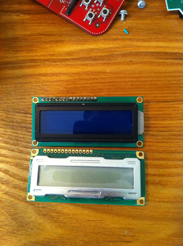
The LCDs came in yesterday. They are basically what I expected them to be minus with one thing with the pin assignment. I planned for this badge to be designed to have the ability to swap out the LCD for 16x2 char one with a backlight. The general layout for the 16x2 is 16 pins for connecting the LCD. The ones I got for the badge are 14 pins. I assumed that the 14 pin on would start in the same place physically on the lcd. (ie. pin 1 - 1) Well, the new lcds start the location of the first input pin at the 16x2 lcd pin 2. This shifts all the pins down by one and looks to make swapping the two types of LCDs very hard or impossible.
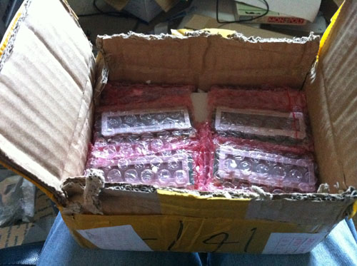
The package they came in looks like a brick of drugs, haha.
Comparison picture. You can see that the header pads don’t match up like I described.
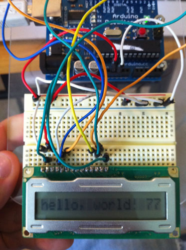
I also started writing some menus and games last night. I am a little disappointed that there is no backlight, but they were pretty cheap and the ones with the backlight were 2 to 3 times more expensive. I will make sure the next version after these will have a backlight LCD.