I was looking at some pictures of the Makerbot the other day and thought it was cool how they used Ethernet cable for connecting some of the boards together. I was also trying to find something useful to do with these LCD’s I had lying around. Then I came up with the idea of driving the LCD over Ethernet cable.
First, I knew that the ST7565 LCD that I was using is a serial LCD, which means I only need 4 or 5 digital pins to drive the LCD. There are 9 total pins total on the LCD including the backlight. Since there is a backlight GND (LED cathode) and a GND to run the display, I really only 8 connections. This is the number of connections in an Ethernet cable.
The pinout for the LCD is:
- /CS - Chip Select
- /RST - Reset
- A0 - sometimes called RS
- SCLK - Serial clock
- SID - Serial Input Data
- VDD - 3.3V power
- GND - ground
- K - LED cathode
- A - LED anode
Making the shield.
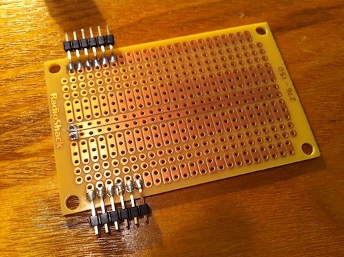
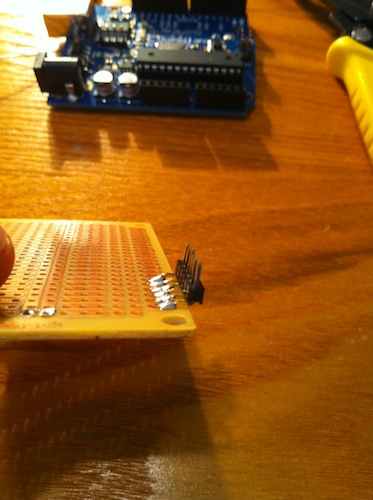
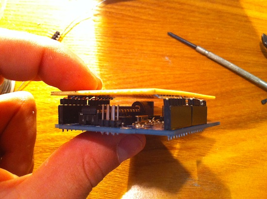
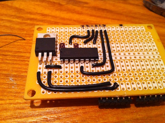
I wanted everything to fit on an arduino shield and not sit on a breadboard. Looking back I should have just bought a prototype shield because it would have been way easier. Since I had a basic RadioShack PCB which is a bit smaller than the arduino but roughly the same size, I decided to use it for the shield. I would not suggest using this for arduino shields. The board is not wide enough. In order to make it fit I needed to bend the male pin headers 90 degrees and then 90 degrees the other way. There are some pictures below that show what I did.
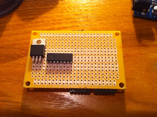
After I had the pins in place, I needed to figure out what I was going to put on the shield. I wanted to be able to use this with arduino clones that may not have the 3.3v output available. I used a LM1117 voltage regulator to drop the voltage to 3.3v. I also needed a 4050 chip that would drop the voltage down from 5v to 3v on the digital pins. The LCD runs on 3.3v so the voltage needs to be dropped down from the arduino. There is also a 100ohm resistor for the backlight. Also wanted to be able to bypass and not use the Ethernet cable if I wanted to so I added some female headers to connect the LCD directly.


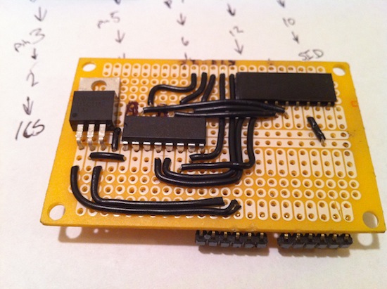
Arduino – 4050
D8 – Pin5 D9 – Pin7 D10 – Pin9 D11 – Pin11 D12 – Pin14
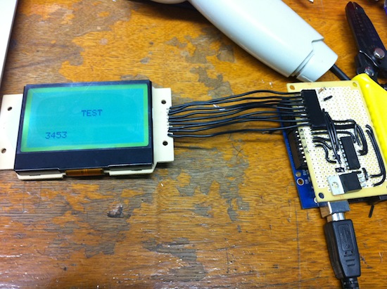
I then took the output pins from the 4050 and connected them to the female header. After hooking up the LCD everything was working.
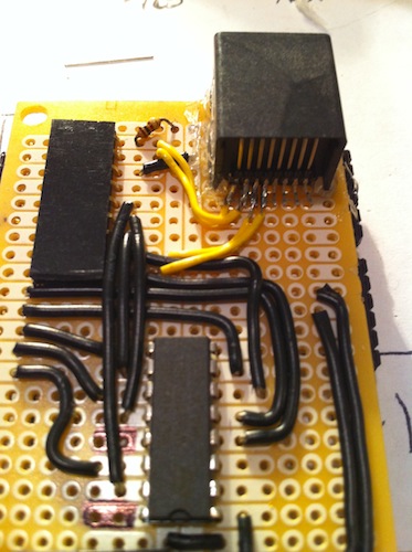
Adding the Ethernet jacks.
Now that the shield was working I needed to add the Ethernet jacks to the board and the LCD. I picked some of these up from mouser. These have the pins tailed out of the back, which is what I needed to be able to solder to them. I ended up hot gluing the jack to the shield. There was really no other way to keep it on the board. After the jack was on, I solder all the connections to the Ethernet leads. This is not for the faint of heart. There were a few times I bridged the pins and it took forever to get them desoldered. I would not attempt this unless you have a nice small soldering tip.
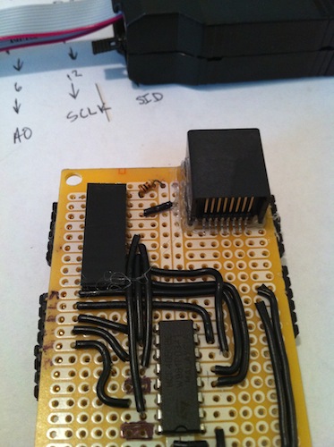
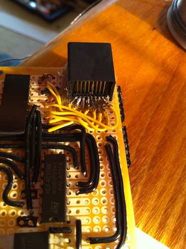
I tested all the connections to make sure they were all good. After that I put a layer of hot glue down to keep them from moving and possibly bridging.
Here is the pins I used for connecting them to Ethernet. (568-B Cable)
Ethernet - LCD
Orange/White – SID Orange – SCLK Green/White – A0 Blue - /RST Blue/White - /CS Green – 3.3v Brown/White – GND Brown – Backlight
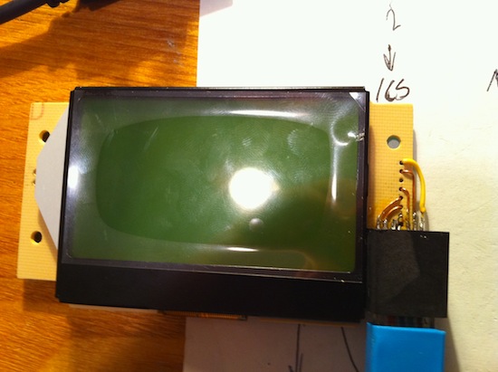
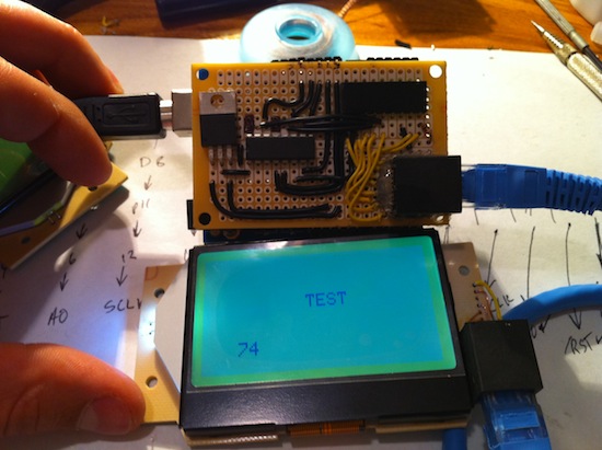
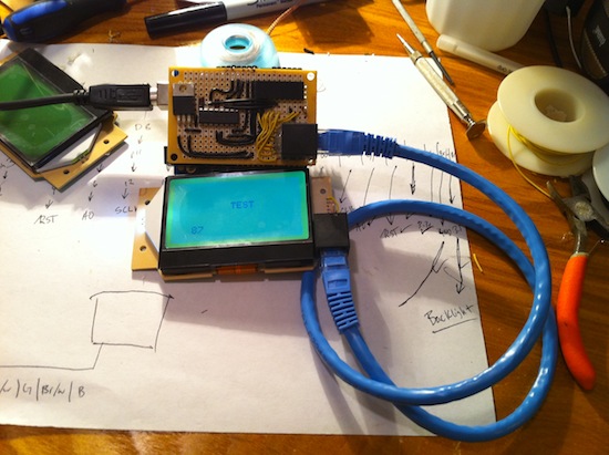
I picked these pins because of how I was able to place the Ethernet jack on the LCD. The /CS pin which was the 4 in from the right, when bent down, fit directly in the hole for the LCD. The rest followed suite when picking placement. This was also a PITA to solder and took some time. After getting those all soldered in and testing the connections, I hot glued the connections like I did on the shield. After plugging it in, everything worked.
Thanks to ladyada for providing awesome documentation on her projects.