Saturday I got a chance to wire up the LCD. As a reference I used a diagram on the Arduino site which looks like this.
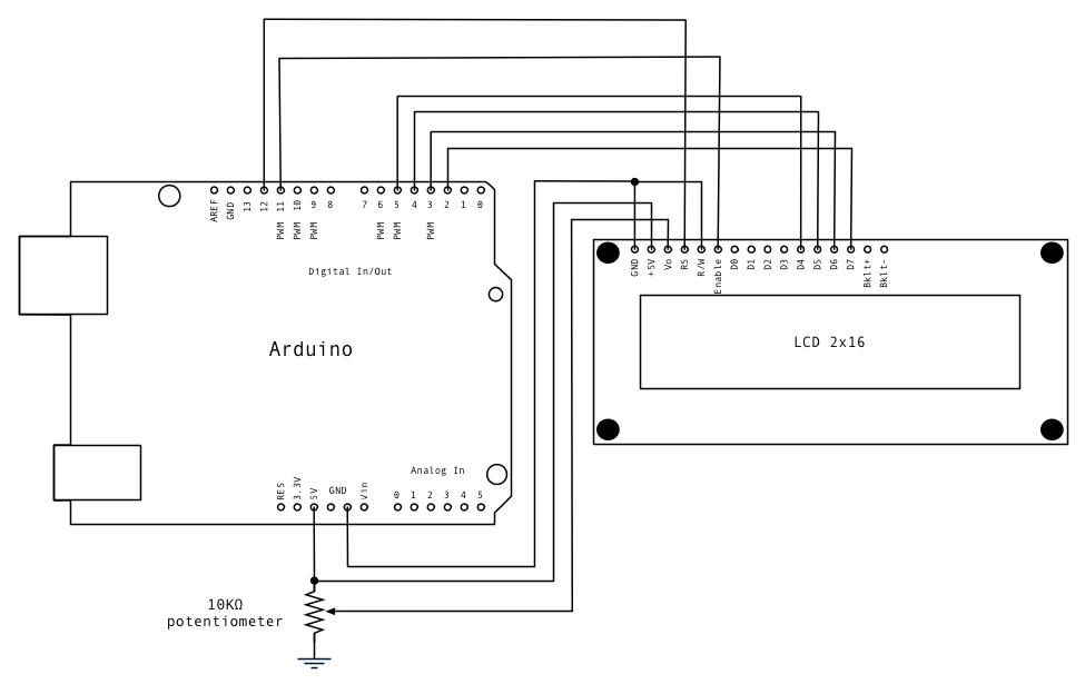
I pretty much used the same scheme as the one posted above with a few changes. I changed pins 12 and 11 to 7 and 6. I did this so that all the outputs could be on one pin header. I wanted the ability to turn the backlight on and off so I added one wire to go from bklt+ to pin 8 and the bklt- to a ground.
When I was testing the LCD the first time, I only had a 100k ohm pot vs the 10k ohm pot that recommended. I went out and got a 10k ohm one from Radio Shack which turned out to work very nicely. The rectangular shape made it perfect to glue underneath the female pin headers on the harness. I used solid core wire for this particular project because I had a lot of it and it works well.
The Harness
The harness consists of:
16 pin female header
Various lengths of solid core wire
9 male header pins
shrink tube (1/16)
10k Ohm Potentiometer
The Pinout
The pinout for the harness is similar to the picture posted above. Moving from left to right (looking down)
GND
One side of the Potentiometer to 5v.
Wiper on Potentiometer
Pin 7 (Arduino)
GND (loop back to pin 1)
Pin 6 (Arduino)
NC
NC
NC
NC
Pin 5 (Arduino)
Pin 4 (Arduino)
Pin 3 (Arduino)
Pin 2 (Arduino)
Pin 8 (Arduino) BL
GND (loop back to pin 1)
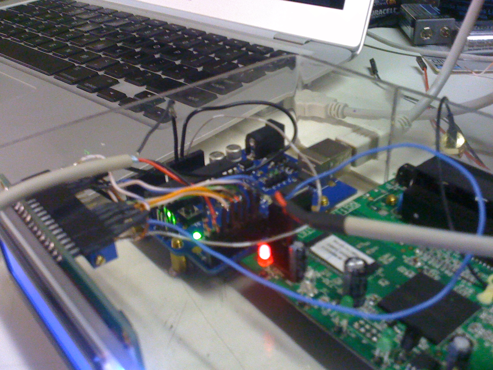
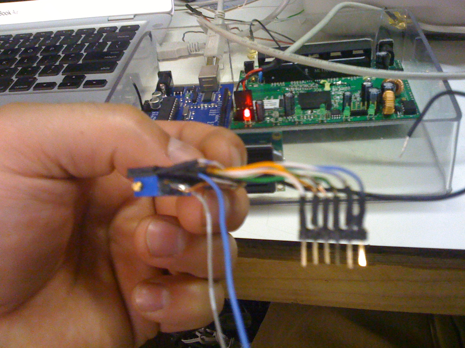
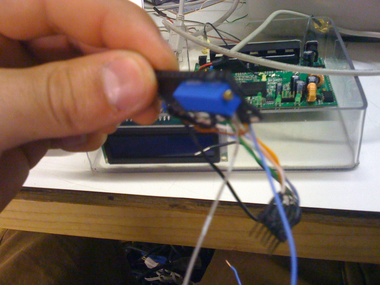
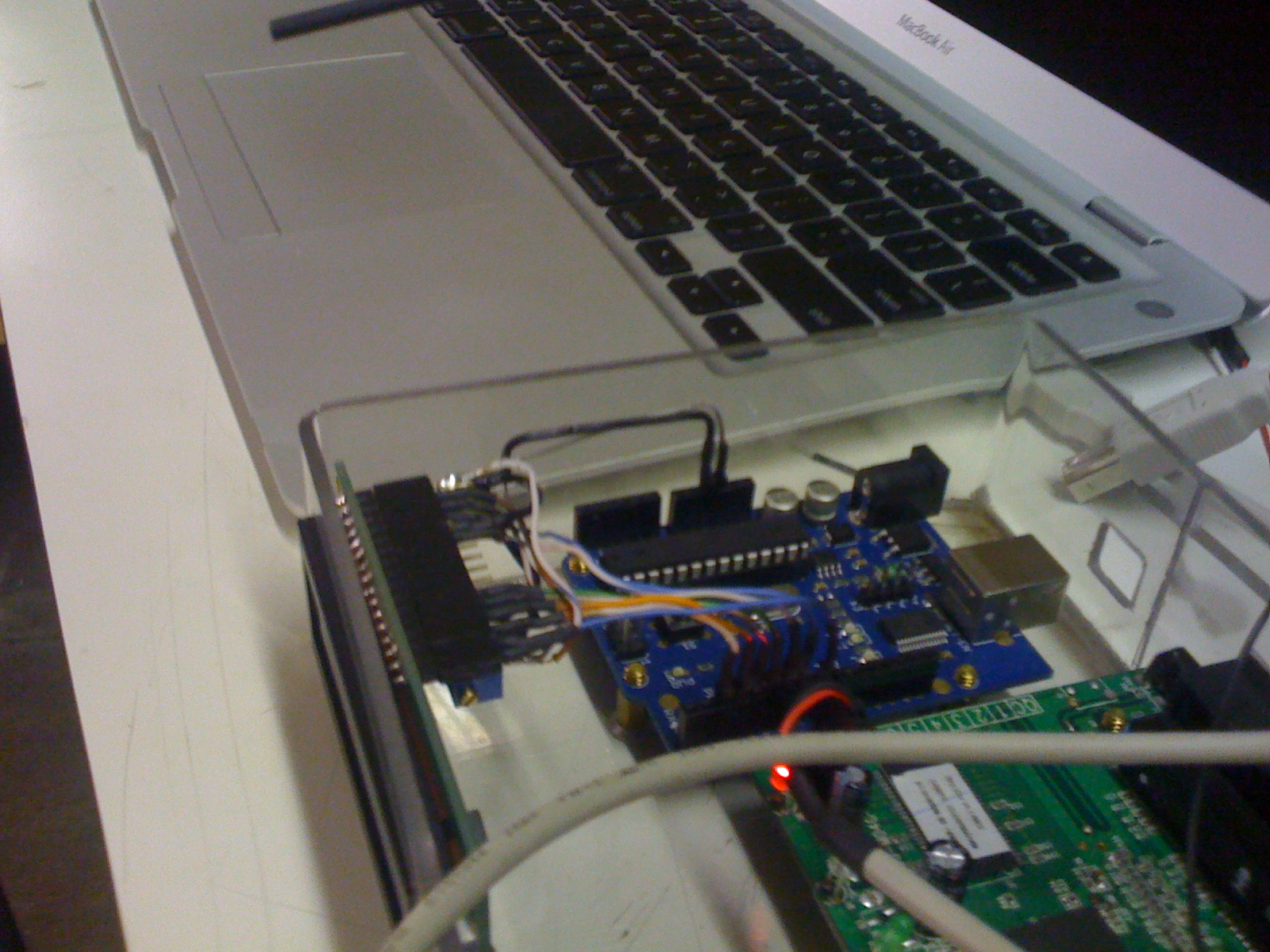
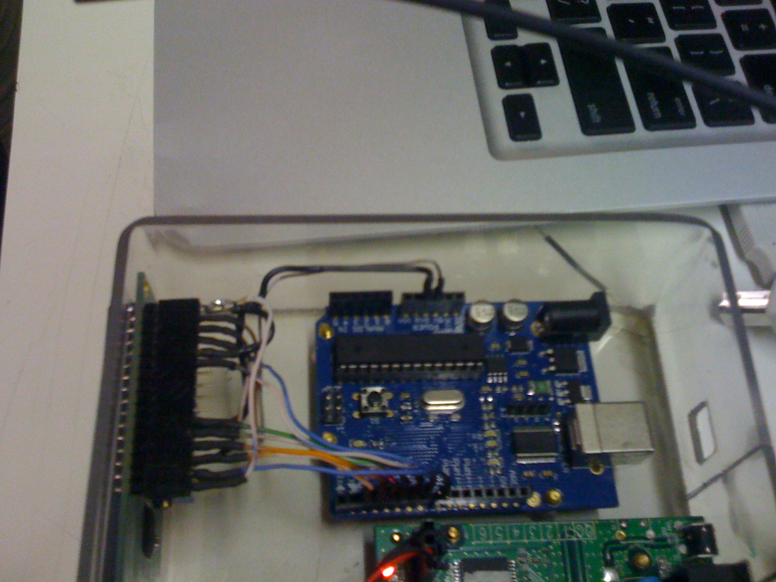
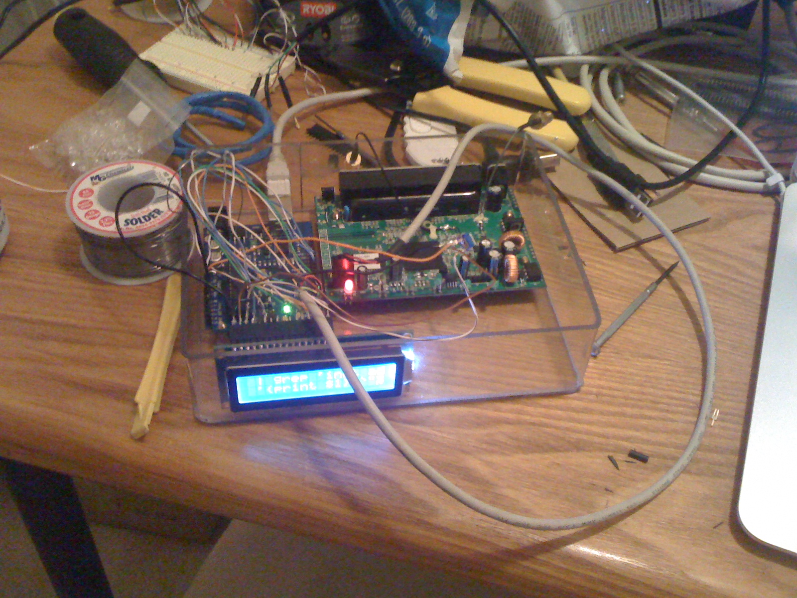
Here are some pictures.